It’s Proxy Time
What is a proxy server? You’ve come to the right place! A proxy server has a special purpose, it acts as an intermediary between a device and the internet. Why is this important? It allows for more privacy, security, and can even allow one to bypass geographical restrictions such as national firewalls.
Today we’re going to be using Cisco Packet Tracer to create a proxy server and you can follow along to see how I do it. Ready? Let’s go!

The Journey Begins
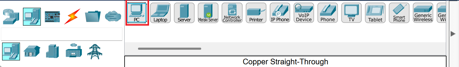
Once you open Cisco Packet Tracer you’ll have a fresh blank canvas. We’re going to start off by placing PC’s on our canvas.
Head to the lower left corner and select end devices and select PC. We’re going to place four computers on our canvas.
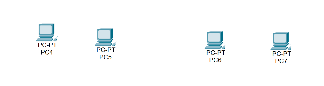
Now we have four computers! Aren’t they beautiful?
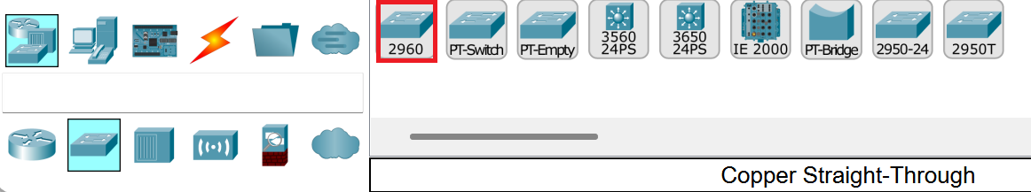
Next, we’re going to place down two switches.
Head to network devices and then to the switch tab. We’re going to select the 2960 and place two of them on our screen.
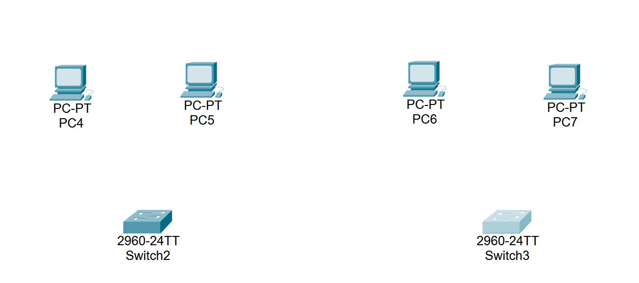
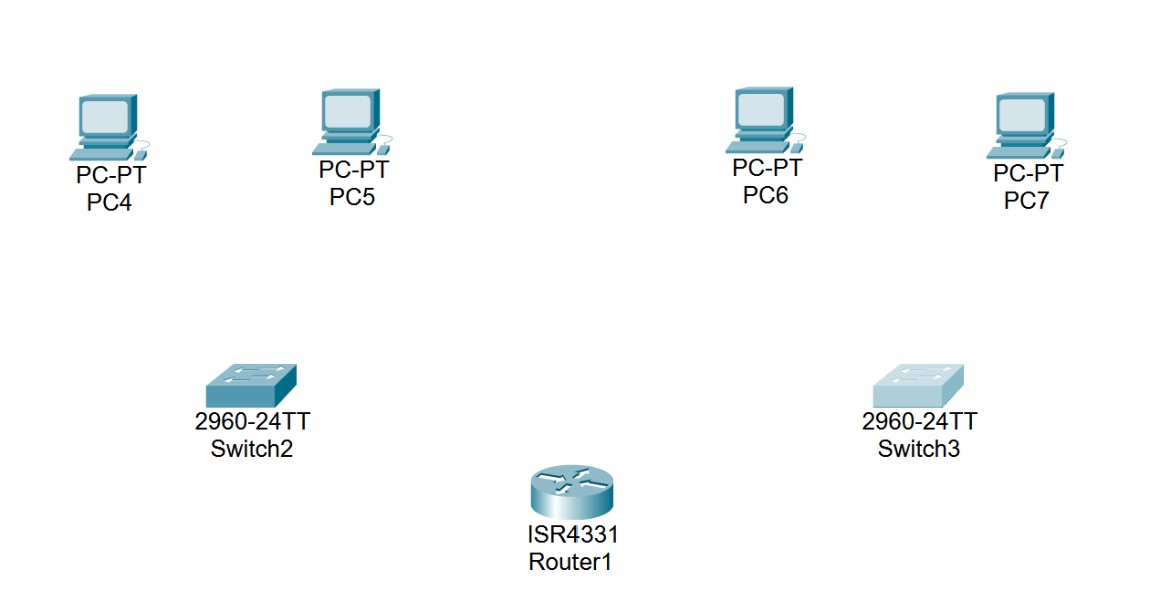
Now we have 2 switches and 4 computers, our ecosystem is growing!
Next, we’re going to add a router to keep our other devices company.
Go to the network devices tab and select router. We’re going to be using the 4331 router today.
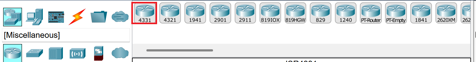
Our network is growing! Isn’t it great?
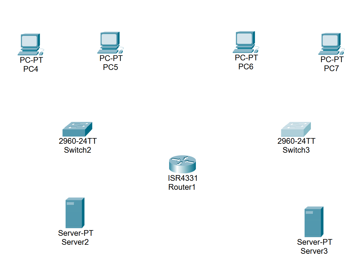
Now we’re going to add two servers to the network. Head to the end devices tab and select server. We’re going to place two of them on the screen.
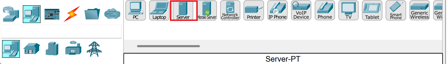
Now our network is finally complete with our servers set up!
It’s Time to Connect
We’re going to start connecting our hardware together and begin configuring it.
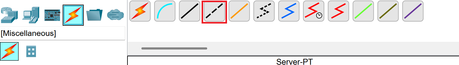
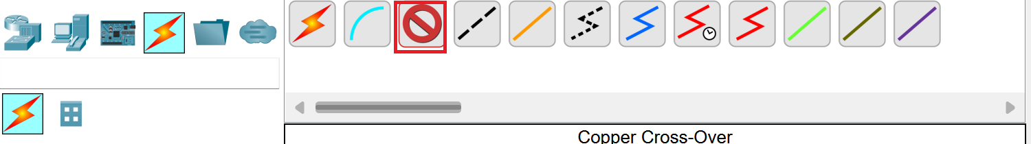
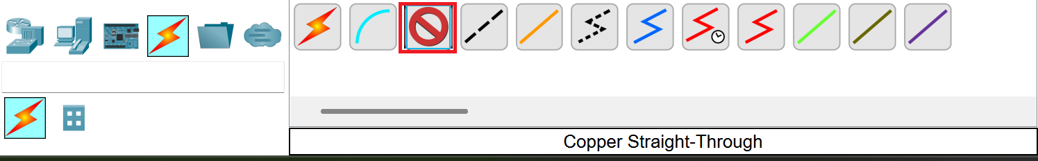
Head to the connections tab and select copper cross-over cable.
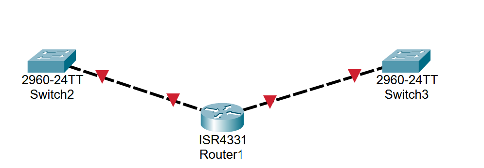
Select the first switch and pick the port fast ethernet 0/1 and attach it to our router. When selecting the router you’ll see giga ethernet 0/0/0, connect to that.


Now head to the other switch and repeat the process with copper cross-over cable. Select the other switch and pick fast ethernet 0/1. Attach it to the router in the port giga ethernet 0/0/1.


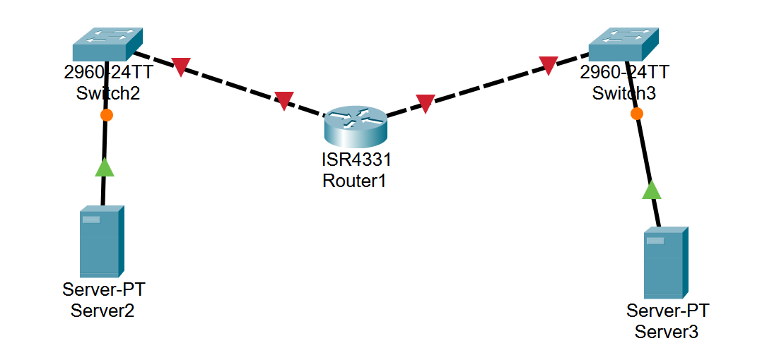
At the end, you should see the switches connected to the router!
Next we’re going to be connecting our switches to the servers.
Go to the connections tab and select copper cross-over cable.
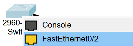
Select the first switch and select fast ethernet 0/2. You’ll then connect it to the first server in the port fast ethernet 0.
Repeat that process with the other server with the same copper cross-over cable.
Now we should have our switches connected to our servers with cables.
Now, we’re going to connect our PC end devices to our switches.
Head to the connections tab and select copper cross-over cable.
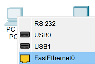
Select the first computer while using the cable and a port called fast ethernet 0 should pop up. Select it.
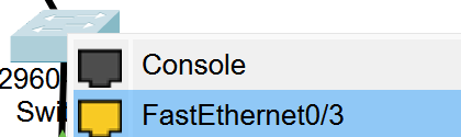
Attach it to the first switch and you should see a port called fast ethernet 0/3.
Repeat this process for the 2nd PC and attach it to the first switch.
After that, head over to the second switch and connect both computers to the second switch.
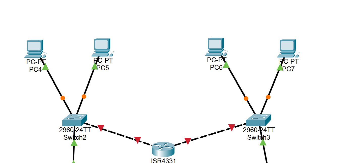
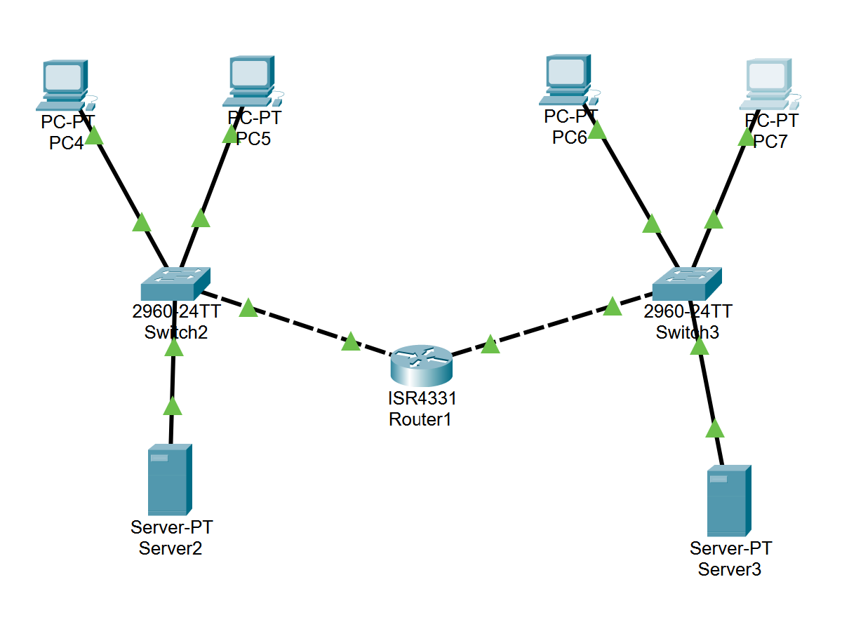
At the end of your process, it should look like this. Do you see how the switches are connected to the PC’s?
Time to Configure
Now comes the complicated part. We’re going to configure all of our devices so they’re communicating properly.
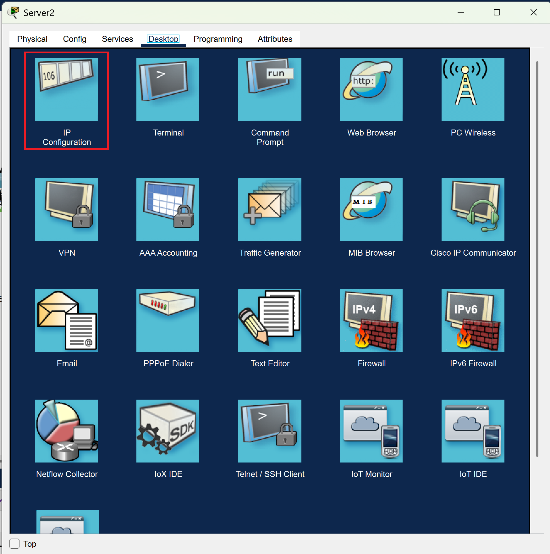
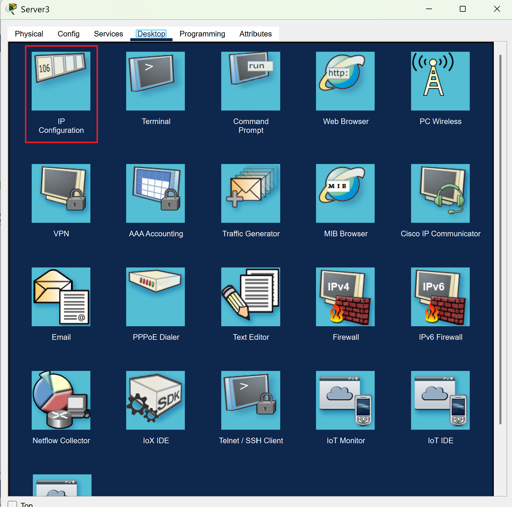
We’re going to start off by selecting our first server and selecting the desktop tab. We’re then going to choose IP Configuration.
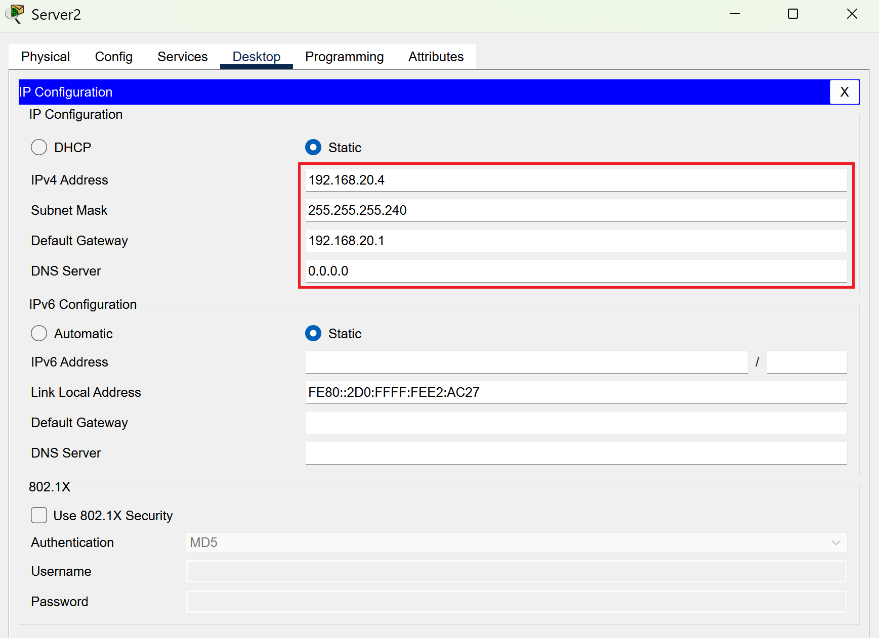
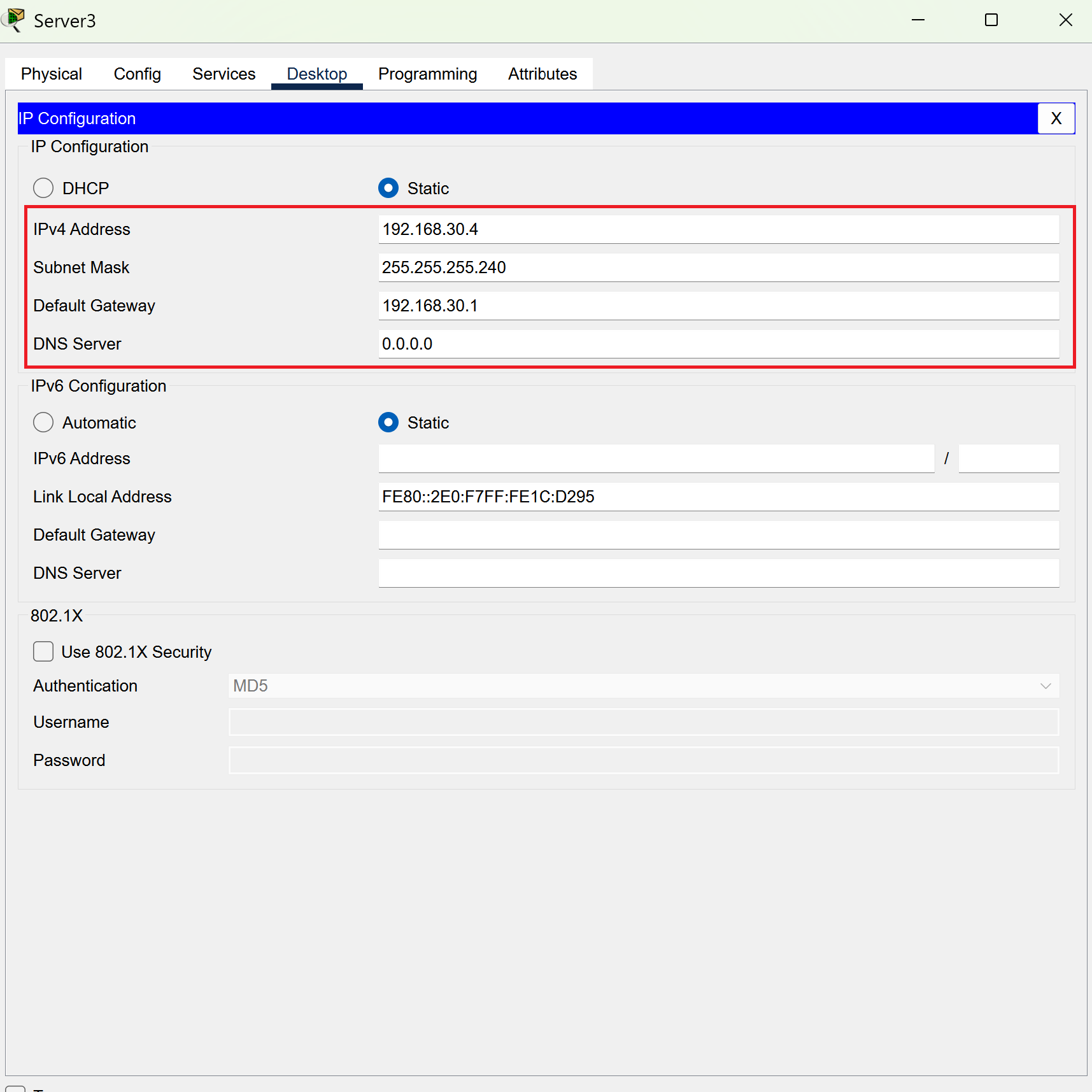
Edit the information in the red box with what I’ve provided. We’re going to change the IPv4 address, gateway, and subnet mask.
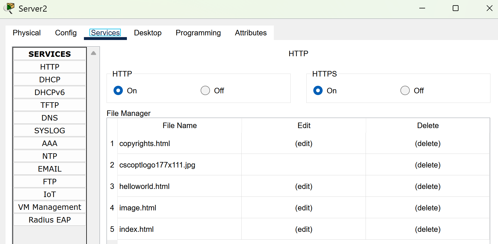
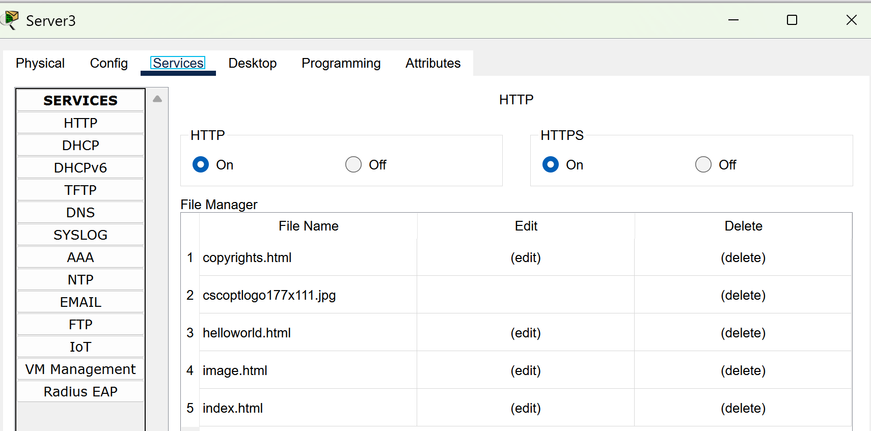
Head to the services tab and see if HTTP and HTTPS are checked on.
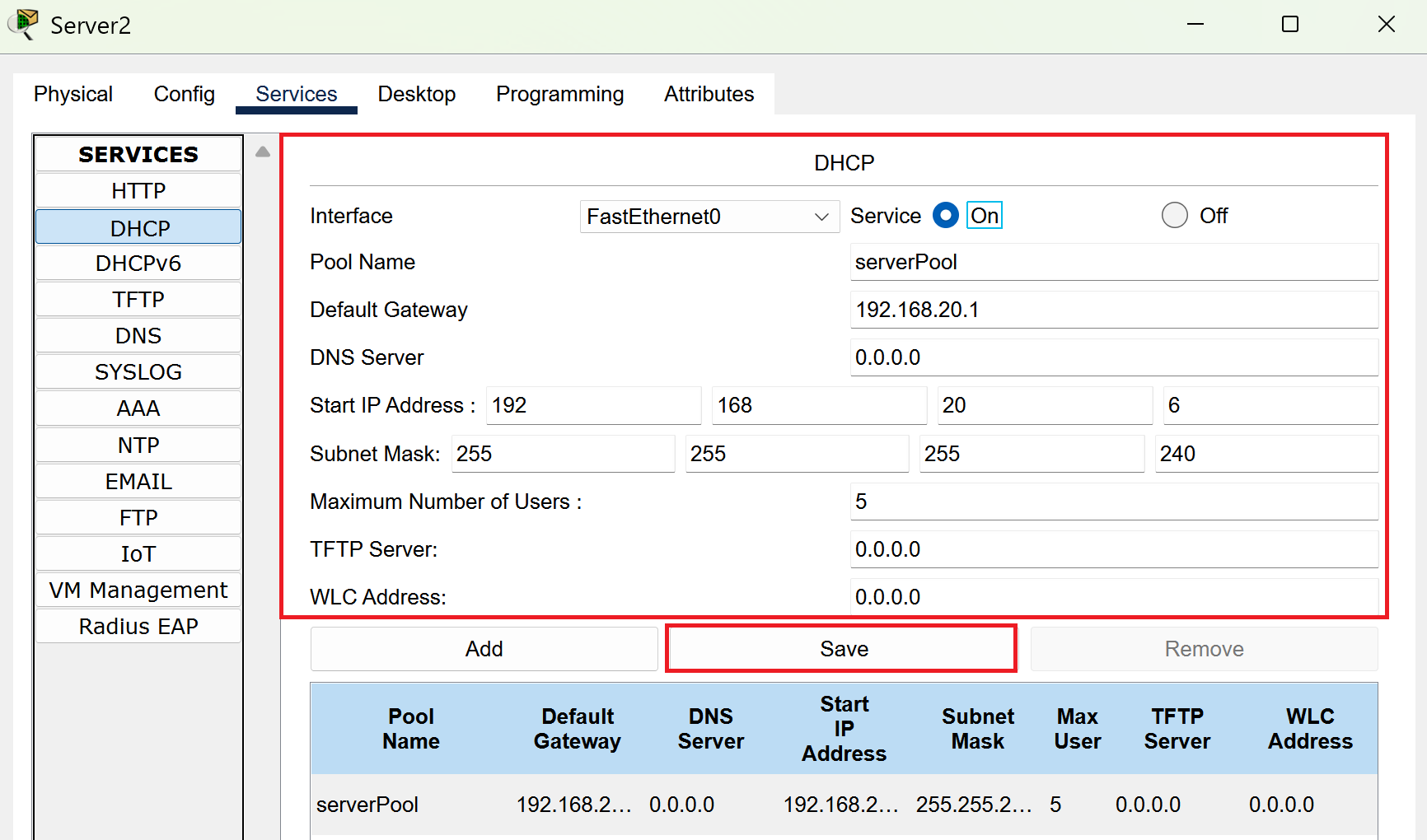
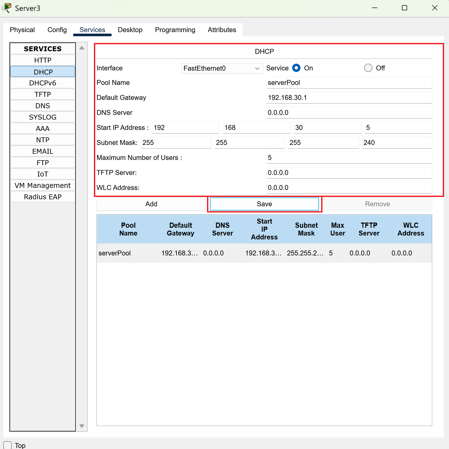
Now head to the DHCP tab and make sure you input all the information that I have provided into your own box.
When you’re done with this process, turn the service to on.
Last but not least, remember to save or all of this was a waste!
Now, head to your other server and we’re going to repeat this process.
Select the desktop tab and select IP Configuration.
Now, make sure that the information in your own box lines up with what I’ve highlighted in red.
Check the services tab and make sure HTTP and HTTPS are checked on.
Now head to the DHCP tab and make sure you input all the information that I have provided into your own box.
When you’re done with this process, turn the service to on.
Last but not least, remember to select save again or all of this was a waste.
It’s Time to Route
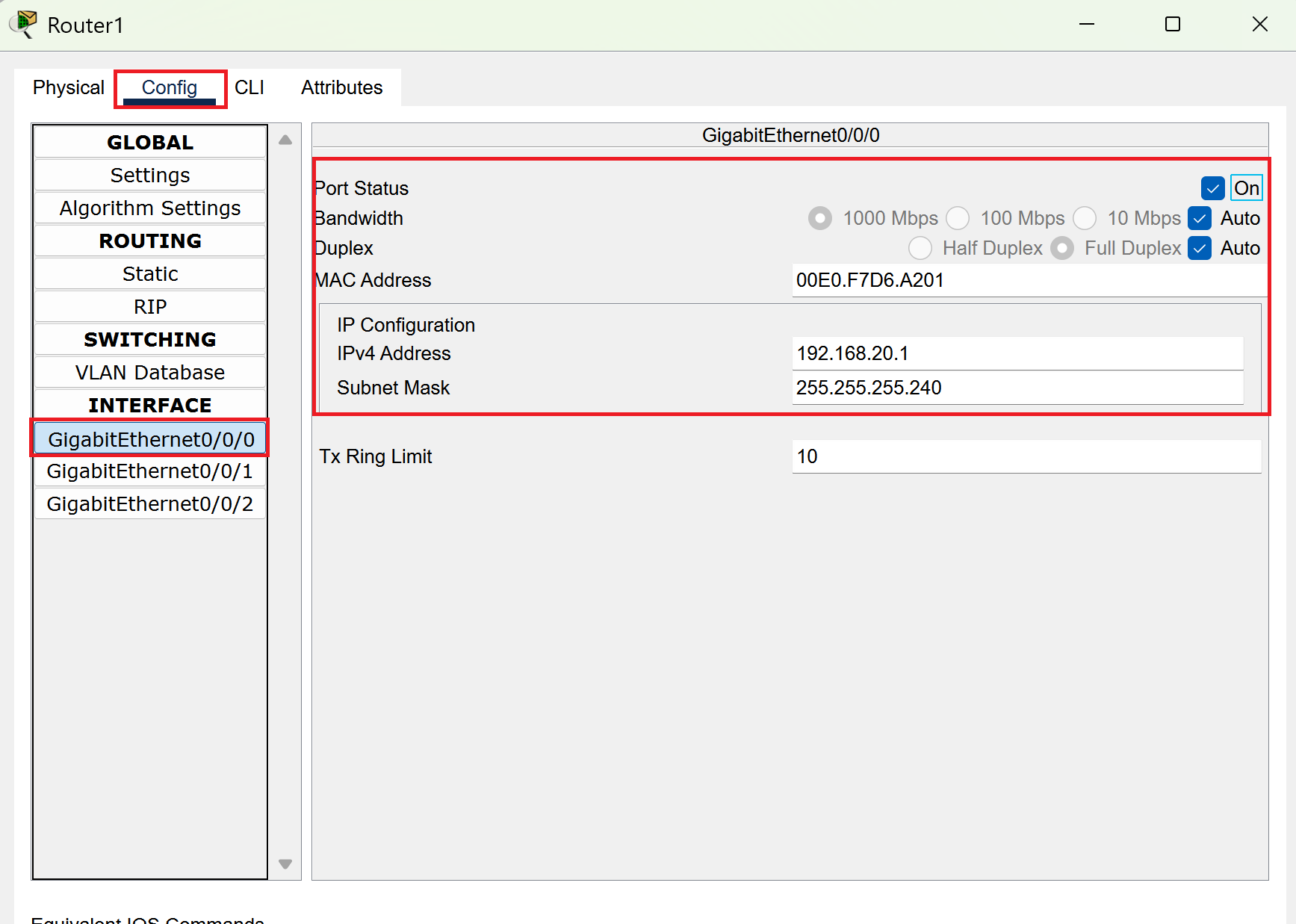
Now head into your router and select the config tab. Under interface you’ll see gigabit ethernet 0/0/0.
Input the information that I have provided in the Ipv4 and subnet mask boxes. Make sure the port status is set to ON.
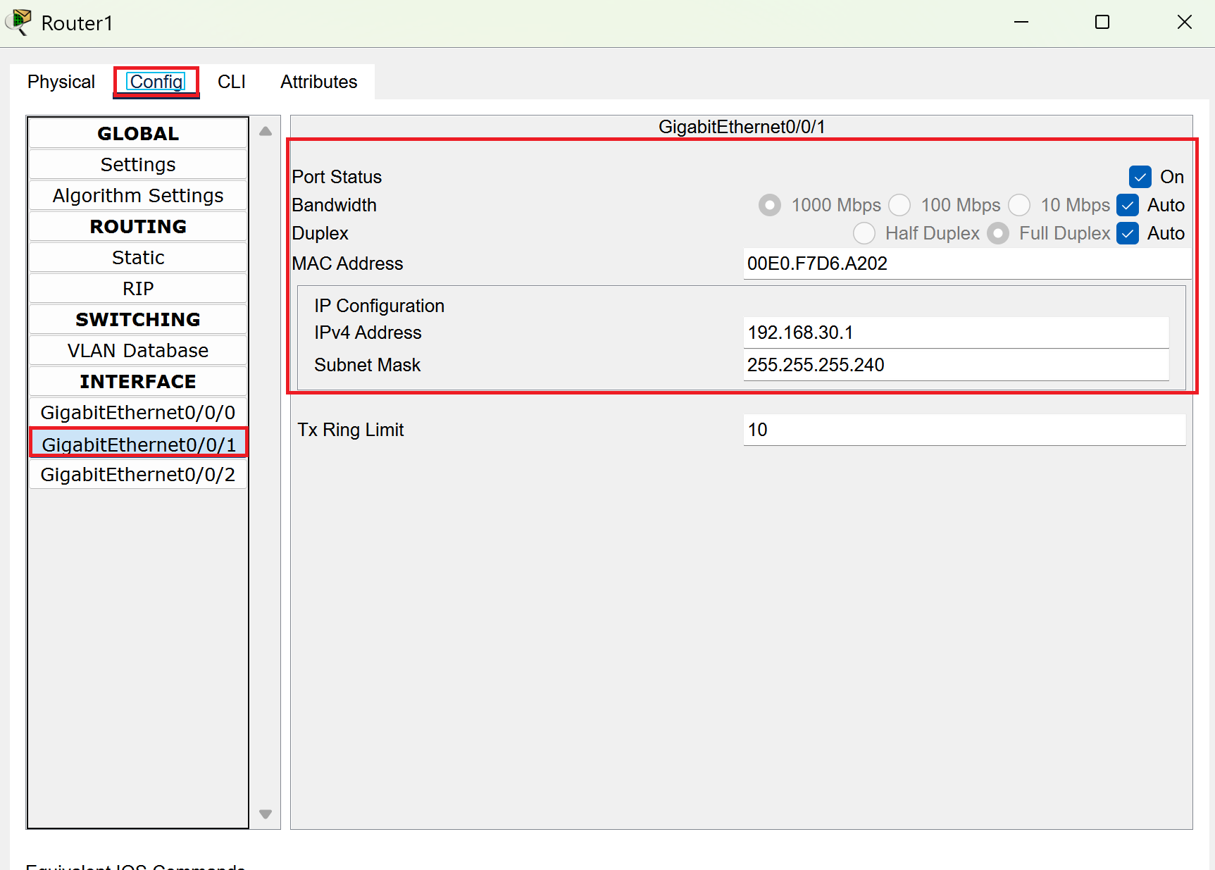
Get ready to repeat the process and head to gigabit ethernet 0/0/1. Change the Ipv4 address and subnet mask. Make sure the port status is ON.
PC Connection
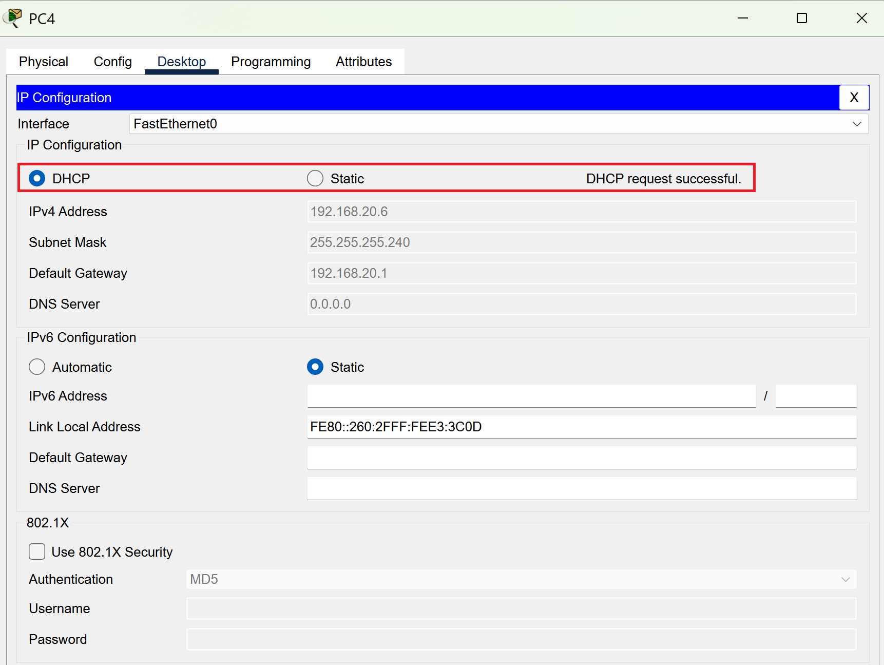
Now it’s time to connect the computers! Select the first PC and select desktop and then IP configuration.
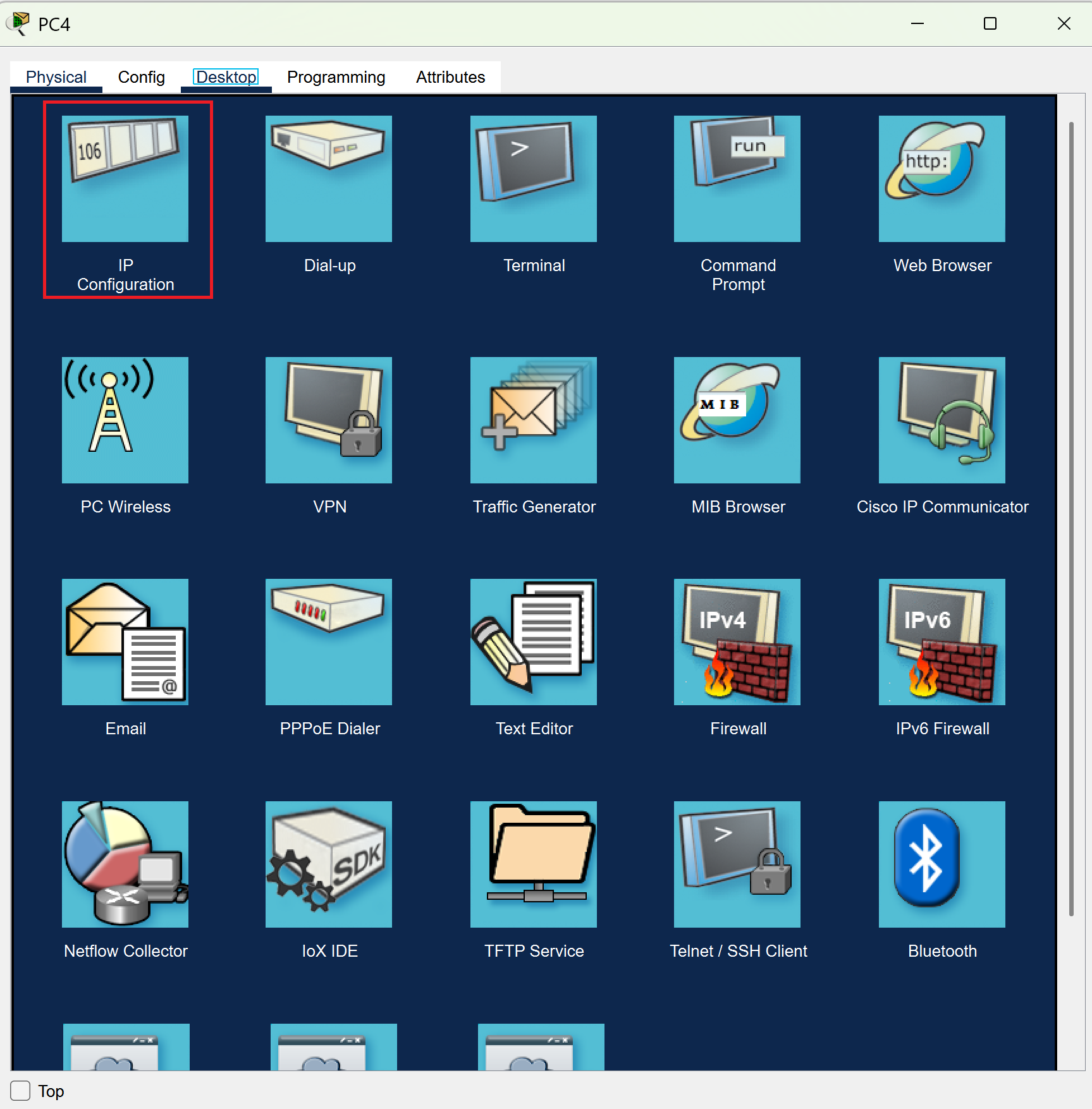
You’ll then see the option under IP configuration to switch from static to dhcp.
Select DHCP and you should see the message of “DHCP request successful”
Now repeat this process for the rest of the PC’s and you should be all done and your network should be all green and running perfectly!
It is Finished!
You did it! You have made a proxy server and configured it! It was a bit of a tedious process but you survived through it. There’s a few advanced options that you can add to your network but I’ll leave it to you to explore and discover what you can do. What’s next on the agenda? No idea, stay tuned to find out more!